Aqua Logic Troubleshooting Guide Aspects of the Aqua Logic that pertain to system setup are not covered in this manual Automation The AQL PS 4 8 16 can control up to 4 8 16 high voltage 120 240V pieces of equipment up to 4 8 for the PS 16 automatic valve actuators and 2 conventional heaters plus a solar heater Both manual and automatic programmed operation
Logic Aqua Logic control unit will also confirm Teach Wireless Successful If this process is not successful then refer to the Trouble shooting section of this manual for additional information 5 Apply labels The Pro Logic and Aqua Logic series of controls allow each output e g AUX1 to be renamed to what is actually being controlled Functionality The AQ CO SERIAL interconnects an RS 232 bus from any Home Automation system with the Aqua Logic PS Pro Logic PS using the powered RS 485 A typical system is shown below
Aqua Logic Troubleshooting Guide
 Aqua Logic Troubleshooting Guide
http://www.bondlogic.co.za/wp-content/uploads/2017/11/BondLogic_LOGO_HighRes.png
System Overview The Aqua Logic is a multifunction pool controller used to fully manage your pool spa system The Aqua Logic can control pumps valves lighting heaters and chlorination Although the Aqua Logic is easy to use it is important to completely read through this operating manual before attempting to operate the control
Templates are pre-designed files or files that can be utilized for various purposes. They can save time and effort by providing a ready-made format and layout for producing different type of material. Templates can be used for individual or expert tasks, such as resumes, invites, leaflets, newsletters, reports, discussions, and more.
Aqua Logic Troubleshooting Guide

Beautiful Texas Hold em Poker Odds Calculator Made With Flutter

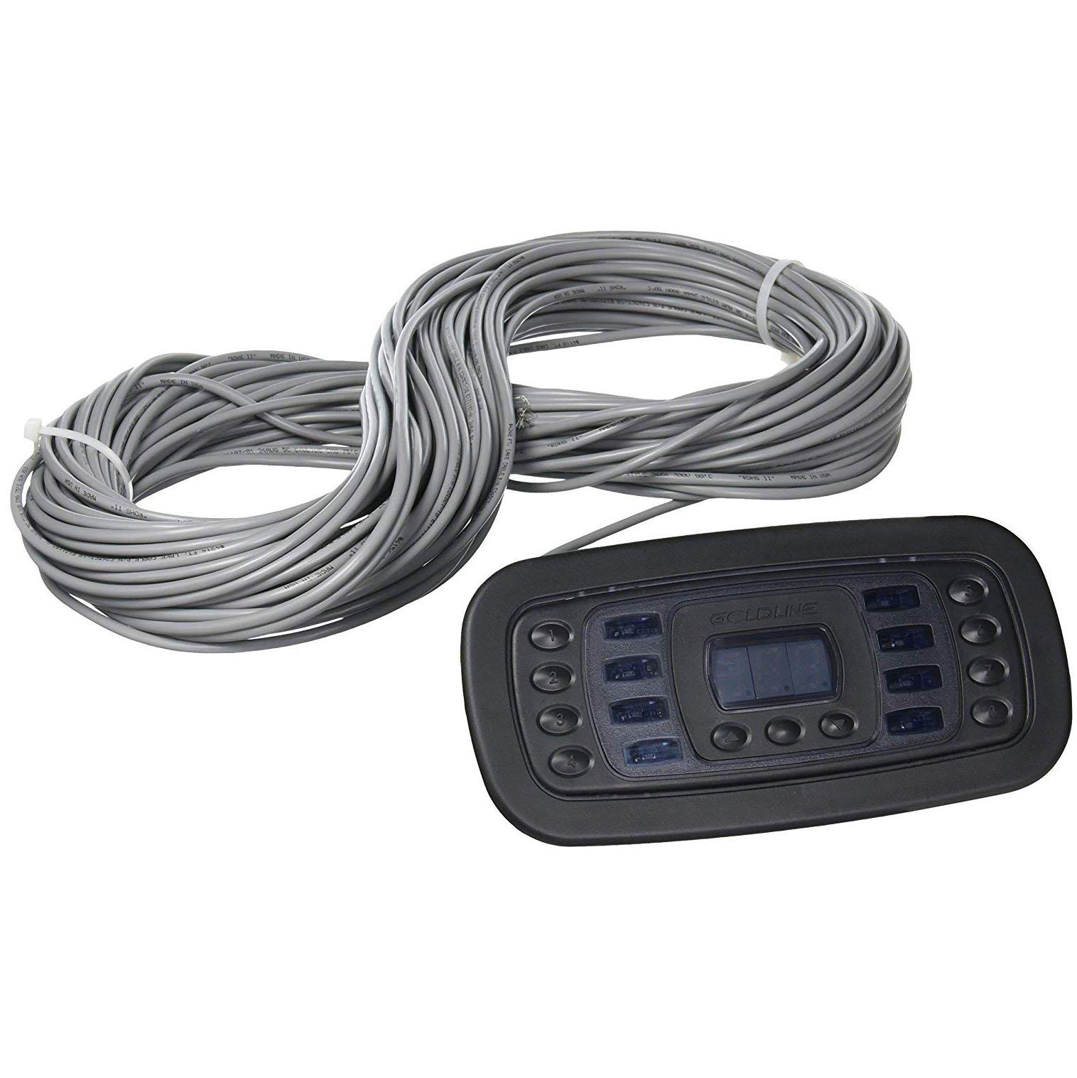
Aqua Plus Pro Logic Remote Controls And Accessories

File Aqua Spout jpg Wikimedia Commons

Contact AQUA Products Services Pvt Ltd

K k Aqua Aura Kvarc extra LAAVA
Aqua Logic In The Swim

https://www.youtube.com/watch?v=yjjlxDKB35E
Detailed guide for troubleshooting the Aqua Plus and Pro Logic pool controllers Please visit https www royalswimmingpools for all your pool needs

https://cdn.dynamixse.com/brownspoolscom/files/1150-AquaLogic_PS-8_System_Operation_Manual.pdf
The Aqua Logic can control pumps valves lighting heaters and chlorination Although the Aqua Logic is easy to use it is important to completely read through this operating manual before attempting to operate the control NOTE This manual assumes that the Aqua Logic has been wired and configured according to the Instal lation Manual

https://hayward.com/support/support-center
Home Support Center Support Center Here you ll gain easy access to information regarding your favorite Hayward products including quick reference guides troubleshooting steps and product support videos You have come to the right place Product brochures manuals downloads more

https://www.hayward-pool.ca/assets/documents/poolscanada/pdf/troubleshooting-guides/ProLogic-Troubleshooting-Guide.pdf
ProLogic Main PCB Layout A I Remote DSP comm RS485 10VDC B Temp sensor terminal block 5VDC C Heater 1 2 terminal block dry contacts D Valves 1 4 4Amp fuse 24VAC E Cell Plug for chlorination F High Voltage Relays top Filter Lights AUX1 AUX2 bottom AUX 3 6 G Flow Monitor flow switch connector H P Transformer Input 120VAC X 2

https://www.manualslib.com/products/Hayward-Aqualogic-8917033.html
We have 2 Hayward AquaLogic manuals available for free PDF download Troubleshooting Manual Hayward AquaLogic Troubleshooting Manual 50 pages Residential Brand Hayward Category Lighting Equipment Size 3 69 MB Table of Contents Table of Contents 3 How Prologic Works Main PCB Layout 4 How to 6
The Aqua Logic can control pumps valves lighting heaters and chlorination Although the Aqua Logic is easy to use it is important to completely read through this operating manual before attempting to operate the control NOTE This manual assumes that the Aqua Logic has been wired and configured according to the Instal lation Manual The remote display keypad with the Pro Logic Aqua Logic Control Center as shown below The maximum wiring distance is 500ft 160m Note that the terminals on both the Pro Logic Aqua Logic main unit and the remote display keypad are numbered Connect 1 to 1 2 to 2 etc If multiple remote display keypads are installed Never connect more than 2
The Aqua Logic is designed to be used as a circuit breaker subpanel for all the pool equipment Run the electrical service from the house s main panel to the Aqua Logic Then install appropriate circuit breakers and wire the pool equipment through the Aqua Logic relays If desired an external subpanel can be used